
SIMULATIONS

SIMULATION SERVICES

AMADE’s research pursues the industry-oriented development of material constitutive models for the reliable simulation of composite materials, bonded joints and, in general, non-linear anisotropic materials. We offer the following services:

  • Expert advising on the simulation of composite materials
  • Guidelines for the use of advanced material models in industry
  • Robust and reliable constitutive models for the simulation of:
    – damage evolution in composite materials (intralaminar damage model)
    – static and fatigue delamination and adhesive joint damage (cohesive zone model)
    – impact events on composite materials and adhesive joints
  • Development of tailor-made material models
  • Customised training at company facilities
COHESIVE ZONE MODEL

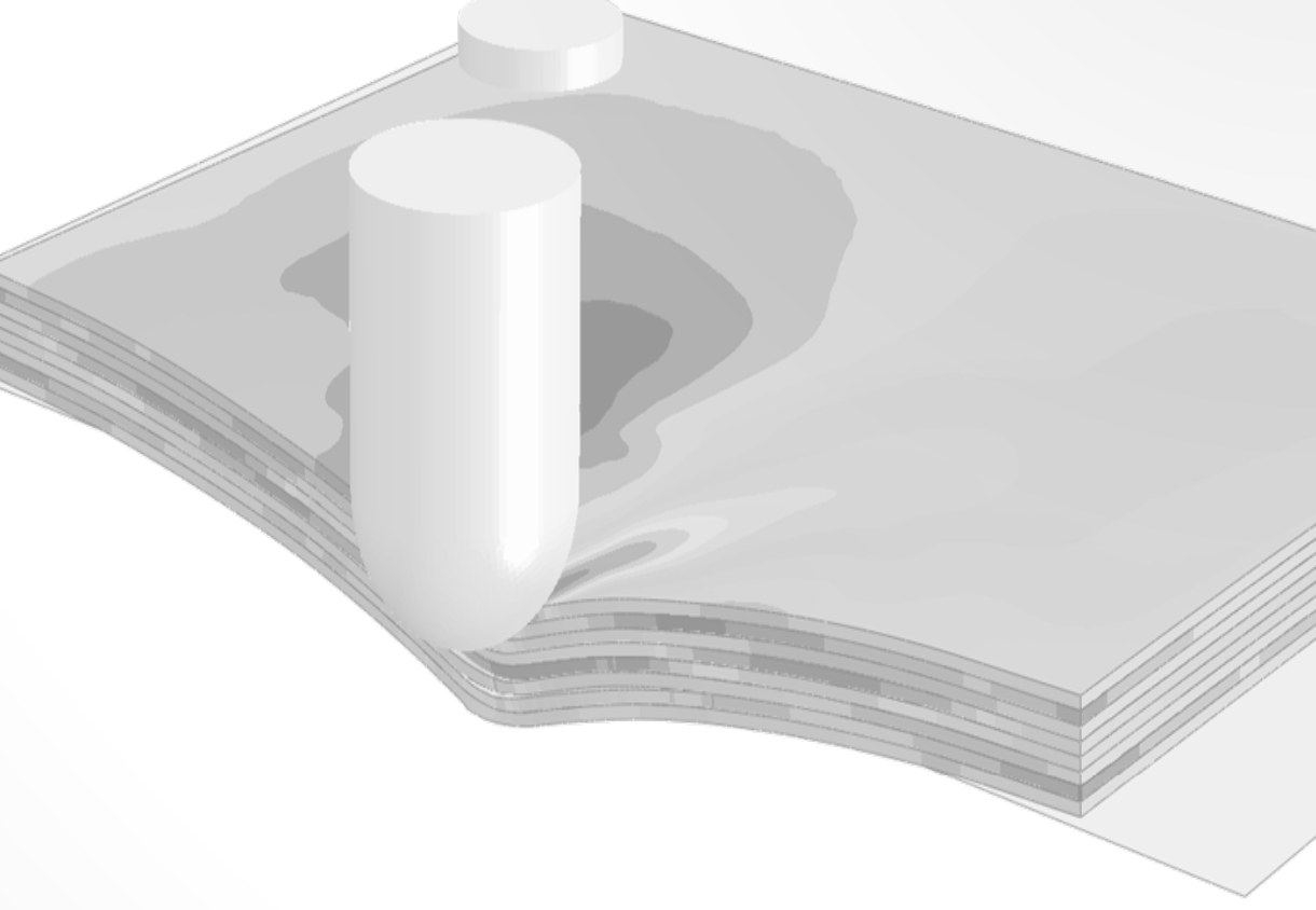
Cohesive zone models allow the modelling of damage at predefined interfaces. They accurately reproduce the fracture process zone and account for both damage initiation and propagation. The main features of AMADE’s cohesive zone model are:

  • Modelling of interlaminar damage: delamination and adhesive joints
  • Static, fatigue and impact loads
  • Consistent mixed-mode behaviour
  • Strategies to use coarse meshes and reduce computational time
  • Implemented and working on Abaqus Standard and Explicit
    User subroutines: UEL | UMAT | UINTER | VUMAT | VUINTER | VUINTERACTION
  • Available to be implemented in other FE software
  • Physically measurable material properties

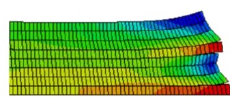
Prediction of free-edge delaminations on a CFRP laminate using cohesive elements

Simulation of a lap adhesive joint with cohesive elements

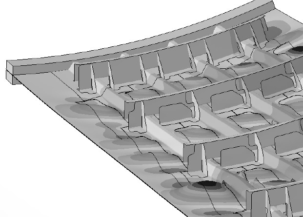
Simulation of stiffener debonding on an impacted composite stiffened panel

INTRALAMINAR DAMAGE MODEL

Thermodynamically consistent damage model for the simulation of progressive intralaminar damage mechanisms in composite materials. The main features of the model are:

  • Modelling of intralaminar matrix and fibre progressive damage
  • Damage activation functions based on LaRC failure criteria
  • Objectivity ensured by Bažant’s crack band model
  • Physically based degradation: the tensile degradation of the fibre is described by two softening branches, linear (fibre bridging) and exponential (fibre pull-out)
  • Large element sizes allowed, by virtue of automatic strength reduction whilst keeping the fracture energy
UNIDIRECTIONAL COMPOSITE LAMINATES
  • Available for shell and 3D solid finite elements
  • Implemented on Abaqus Standard and Explicit
    User subroutines: UMAT | VUMAT
  • Implemented on LS-DYNA
    Material model “MAT_262: Laminated Fracture Daimler Camanho”
  • Available to be implemented in other FE software
WOVEN COMPOSITE LAMINATES
  • Available for shell finite elements
  • Implemented on Abaqus Explicit
    User subroutine: VUMAT
  • Available to be implemented in other FE software

Simulation of damage evolution in a compression after impact (CAI) test

SIMULATION OF IMPACT EVENTS

Impact events are a design limitation in most structural elements. Combining AMADE’s intralaminar and interlaminar damage models, implemented in explicit finite element codes, impact events on composite materials can be reliably simulated.

  • Reliable simulation of impact-induced damage, with good correlation in both damage extent and load-displacement response
  • Modelling strategies for improved computational time
  • Implemented and working on Abaqus Explicit
    User subroutines: VUMAT | VUINTER | VUINTERACTION
  • Available to be implemented in other FE software

Load vs time during an impact event: experimental data and numerical prediction

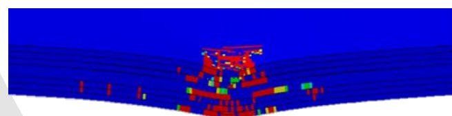
Simulation, intralaminar damage

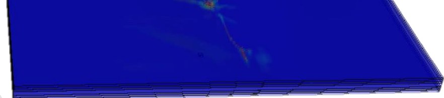
Simulation, delaminations

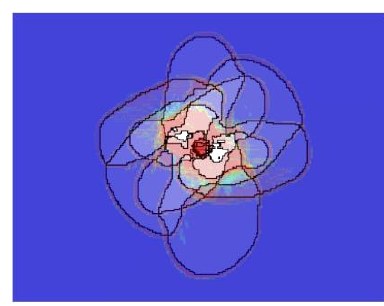
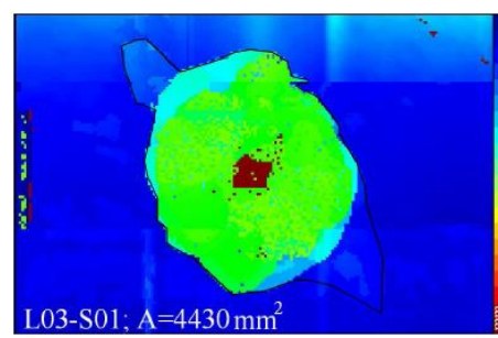
Experimental (C-scan), delaminations

MATERIAL PROPERTIES IDENTIFICATION

The material models developed at AMADE rely on physically measurable material properties that can be obtained in our testing lab, mostly by means of standardised tests. The tables give guidelines on the required properties and how to measure them.

ELASTIC PROPERTIES
E11 Young’s modulus, fibre direction Tensile test, fibre direction
E22, E33 Young’s moduli, transverse direction Tensile test, transverse direction
G12, G13 In-plane shear moduli In-plane shear ±45º | Iosipescu tests
G23 Transverse shear modulus Resin shear modulus | Iosipescu test
ν12, ν13 In-plane Poisson’s ratios Tensile test
ν23 Transverse Poisson’s ratio Computed (transverse isotropy plane)
STRENGTH PROPERTIES
XT Tensile strength, fibre direction Tensile test, fibre direction
XC Compressive strength, fibre direction Compression test, fibre direction
YT Tensile strength, transverse direction Tensile test, transverse direction
YC Compressive strength, transverse direction Compression test, transverse direction
SL Shear strength In-plane shear ±45º | Iosipescu tests
COHESIVE MODEL PROPERTIES
GIc Fracture toughness, mode I DCB test
GIIc Fracture toughness, mode II ENF or C-ELS tests
Gc Fracture toughness, mixed mode MMB test
σnmax Interlaminar strength, mode I Tensile test / ILTS test (bulk matrix / adhesive)
σtmax Interlaminar strength, mode II Interlaminar shear (ILSS) test (bulk matrix / adhesive)
INTRALAMINAR MODEL PROPERTIES
GXT Fibre fracture toughness, tension Compact tension or double edge notch tension
GXC Fibre fracture toughness, compression Compact compression or double edge notch compression
GYT Matrix fracture toughness, tension DCB test (same as GIc)
GYC Matrix fracture toughness, compression Computed: GYC = GSL / cos(53º)
GSL Matrix fracture toughness, shear ENF or C-ELS tests (same as GIIc)

Do you need a specific inspection or simulation? Let us know your needs: testlab.amade@udg.edu | +34 972 419 690

Overview

This website uses cookies so that we can provide you with the best user experience possible. Cookie information is stored in your browser and performs functions such as recognising you when you return to our website and helping our team to understand which sections of the website you find most interesting and useful.

You can check our privacy policy and our cookie policy.